The physio-chemical and biological characterization of the shell of the golden mussel increases our knowledge about biomineralized stuctures. The shell is composed of a hierachical structure with specific functions working together and is reflected in its mechanical and biological properties
This information could be key to the control of this inasive species. Fully understanding the processes involved in the process of shell production, researchers can suggest specific effective methods for controlling the species based on inherent necessities to the species and the physical and molecular support factors. Along with this, the process could inspire the creation of new products and technologies for example in Material technologies and tissue engineering, aeronautics and electronics.
Scanning electron microscope:
The scanning electron microscope (SEM) produces images of a sample by bombarding it with a stream of electrons. The electrons interact with the atoms of the sample emiting X-rays that are detected and that, by their specific energy, indicate the semi-quantatative composition of the surface of the sample. This technic together with the SEM is called EDS, energy dispersive spectroscopy.
In the SEM-EDS tests, shell samples are mechanically fragmented and then fixed to a slide with carbon tape and silver paint to make electric contact, and covered with a thin film (nanometric) of gold-palladium bonds, permiting the visualization of all the surfaces of the fragments. As the sample is dielectrica (insolator), the electrons are moved via the carbon tape and silver paint.
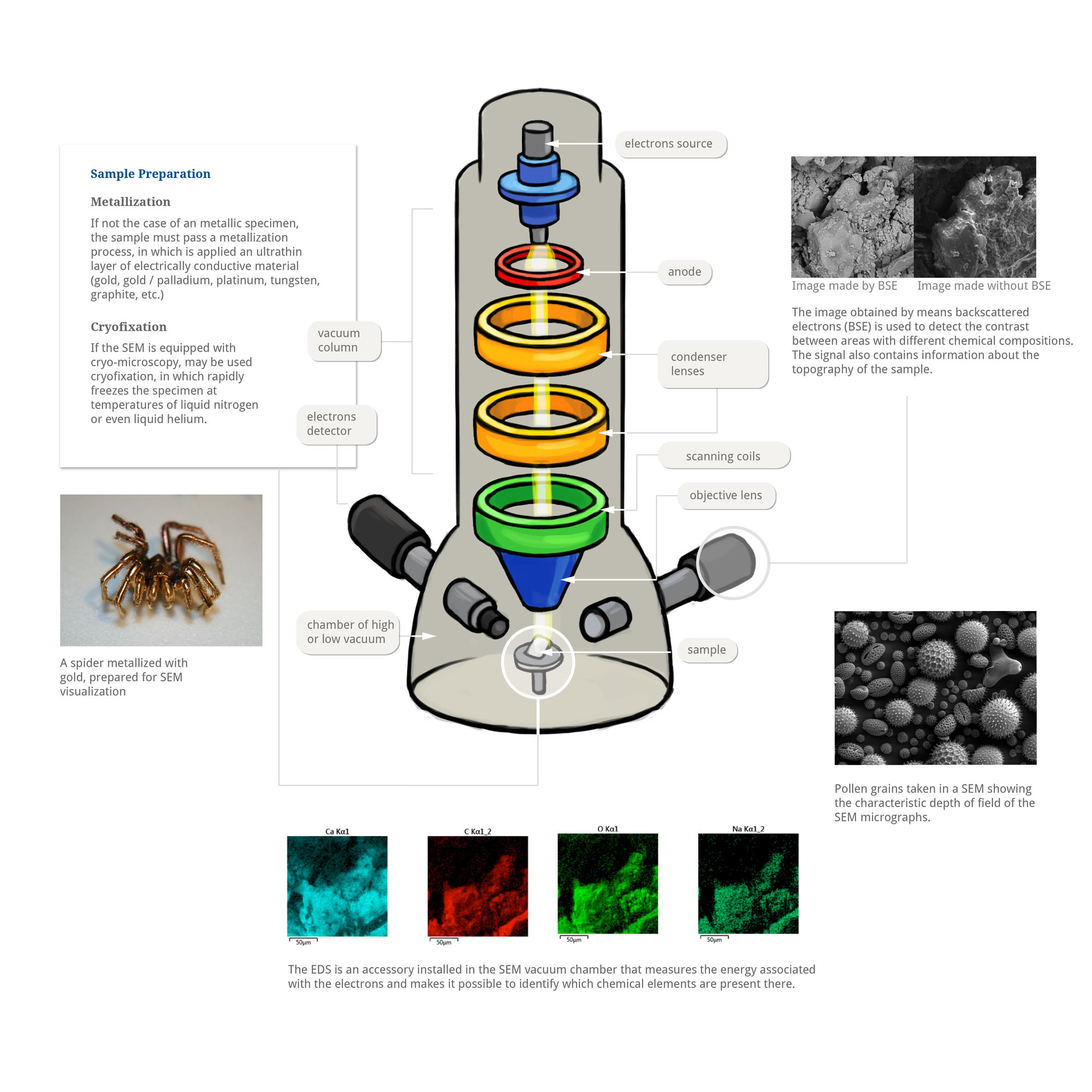
Figure 5.12: Schematic of a Scanning electron microscope
In a typical SEM, electrons are emitted from a (generally) tungston filament that acts as a cathode, with an energy potential varying from 0,5 a 30KV, and accelorated with an anode, been also possibe to obtain electrons by the field emmision effect (gun).Tungsten is normally used in thermionic electron guns because it has the highest melting point and lowest vapour pressure of all metals, thereby allowing it to be heated for electron emission. The electron beam is focused by one or two condenser lenses, in a beam of between 0,4 and 0,5nm. The beam passes through pairs of scanning coils or pairs of deflector plates in the electron column. When the primary electron beam interacts with the sample, the electrons lose energy by dispertion and absorption; the interaction between the electron beam and the sample results in the emission of secondary electrons, backscattered electrons, Auger electrons, Bremstralung X-rays, X-rays, electromagnetic radiation in the infrared, visible and ultraviolet bands, photons along with heating up the sample.
SEM images have a virtual aspect to them because they are observed on the monitor of the apparatus is transcodificated from the energy emmitted by the electrons, to the contrary of visible light radiation.
Transmission electron microscopy:
Transmission electron microscopy (TEM) is a microscope where a beam of electrons is emmitted at an ultra thin sample, interacting with the sample during passage. The interaction of the electrons transmitted through the sample form an image that is magnified and focused onto an imaging device. Like other electronoc microscopes, the TEM is capable of showing images with a significantly higher resolution, when compared to optical microscopes, due to the wavelength of the electron beam – the TEM also permits the observation of atomic organization in crystaline structures.
At smaller magnifications TEM image contrast is due to absorption of electrons in the material, due to the thickness and composition of the material. At higher magnifications complex wave interactions modulate the intensity of the image, requiring expert analysis of observed images. Alternate modes of use allow for the TEM to observe modulations in chemical identity, crystal orientation, electronic structure and sample induced electron phase shift as well as the regular absorption based imaging.

Figure 5.13: Schematic of a Transmission electron microscopy
Atomic force microscopy:
Atomic force microscopy (AFM)is a very high-resolution type of Scanning probe microscopy (SPM), with demonstrated resolution on the order of fractions of a nanometer. The information is collected by “feeling” the surface with a mechanical probe.
The measurements of the layer topography were done in the air using tapping mode,using a silicon probe with a cylidric head with a radius of 6nm. Before, the shell samples were cleaned and covered in resin, cut and polished to allow a transversal view of the layers.
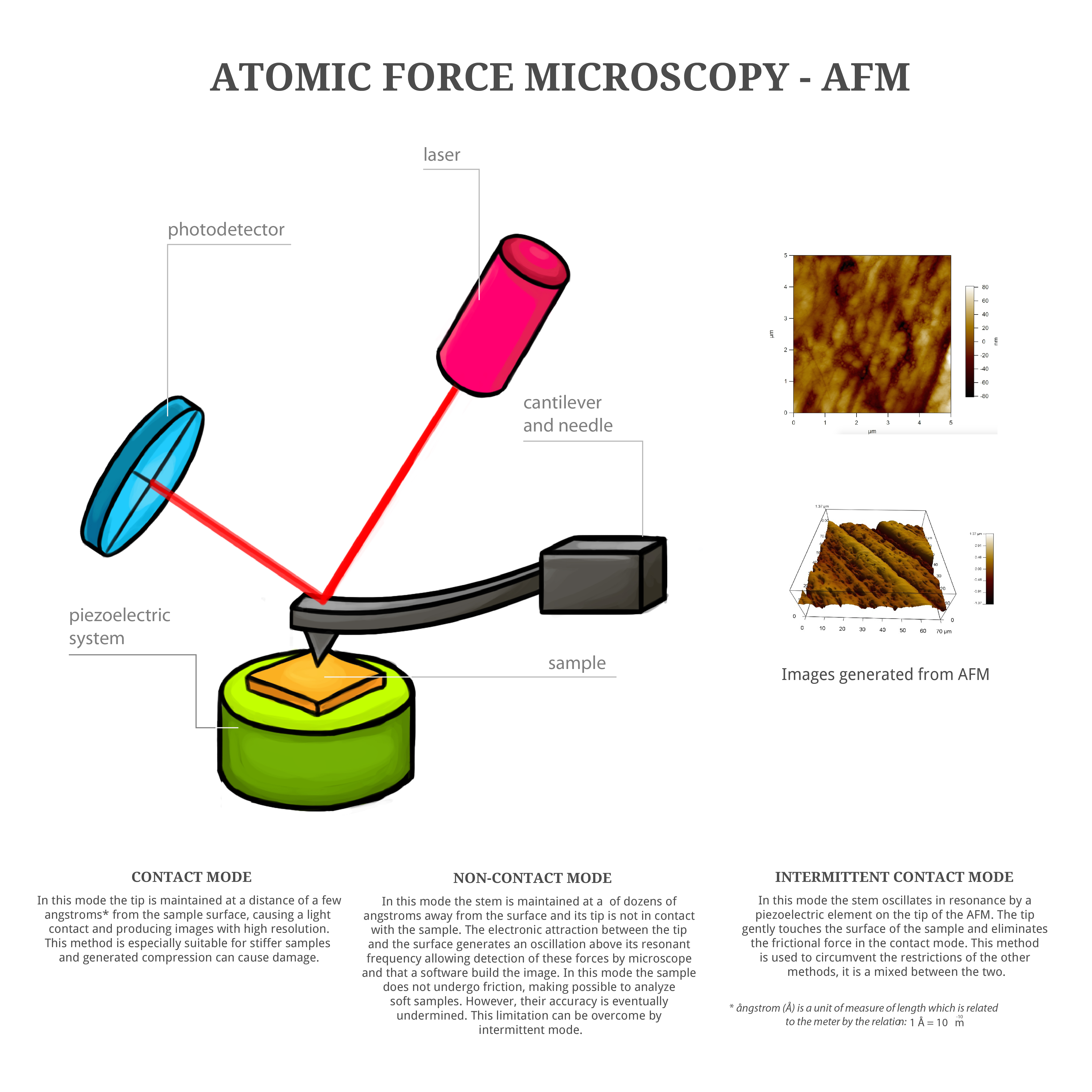
Figura 5.14: Representation of an Atomic Force Microscopy probe and how it works.
X-Ray Diffraction:
X-Ray Diffraction (XRD) of well-determined wavelength (produced by an X-rays tube), it is used in crystal analysis. When this defined beam diffracts in an unknown crystal, the measurement of the emerging ray diffraction angle can elucidate the distance of the atoms in the crystal and hence the crystal structure.
To determine the calcium carbonate phase(CaCO3) that composes the shell, qualitative tests were performed using an X-rays diffractometer with a horizontal goniometer (θ-2θ). The tests were performed with shell powder, obtained by grinding with pestle and mortar, and undamaged shells, in which the tests were performed on internal and external areas (dorsal and ventral) of the shell. The diffraction patterns obtained were compared with the basic crystallographic records that make up the database of the International Centre for Diffraction Data (ICDD) available with the equipment’s software.

Figure 5.15: Chamber of X-rays.
Mechanical tests:
The mechanical properties of a material can be determined through several mechanical tests. The tests can have static characteristics, when the static resistence to which the material can resist is measured, or dynamic characteristics, when the material’s mechanical response to a test varies as a function of time.
For the test on the golden mussel shell, the small dimensions of the shell were a limiting factor, making it impossible to prepare a set of tests conforming to pre-established parameters for testing. The Vicker’s hardness test – indentation – is the most indicated test because it is a non destructive whose dent is made with a small (micrometers) diamond point. The test consists consists of a tiny diamond indenter, shaped like a pyramidal diamond with an angle of 136º between opposing faces. The resulting dent is observed with a microscope and measured. This is converted into a hardness index HV. Due to its versatility, the indentation test can also be used to evaluate other mechanical properties, like the elasticity modulus (Young’s modulus), ultimate tensile strength limits and fracture resistance.

Both the tensile strength limit and the hardness are indicators of the resistance of a material to plastic deformation, therefore, they are substantially proportional: using the stress-strain graph we can determine the elastic modulus.
The base of the indentation technique to obtain values of toughness is the series of cracks formed under a heavy load. The size of the cracks produced by this technique is an inverse function of toughness. The fracture toughness of a material is related to the level of elastic tension which can be reached around the end of the crack before the fracture process begins. That is, the elastic ability to withstand the stresses before generating the fracture.